Introduction #
This white paper is intended for VCPP Cloud Providers who need guidance on how to configure Google Cloud VMware Engine with VMware Cloud Director service (CDs). The content below describes the manual deployment process required to setup the Google Cloud projects, configure them, deploy a Software Defined Data Center (SDDC), associate it to CDs, and the process to configure a virtual private network (VPN) solution for connectivity to isolated networks.
A virtual private network (VPN) provides traffic tunneling through an encrypted connection, preventing it from being seen or modified in transit. VMware NSX® Data Center for vSphere includes a remote access VPN feature (IPsec) that allows the connection from a remote site to connect securely to the private networks and applications in the organization virtual data center.
Due to a limitation in VPN technology in Google Cloud, the provider will need to select an alternative solution such as an open source or commercially available, depending on the required features and available support. Examples of open source solutions include OpenVPN or StrongSwan. This deployment guide will walk through the steps required to implement the StrongSwan solution to provide the VPN connectivity between the provider-managed customer project and the T1 edge that sits in front of the tenant networks. The VPN solution is deployed and configured manually in addition to being managed separately from CDs.
Disclamer
VMware does not endorse, recommend, or support any third-party utility or solution.
A general knowledge of networking and security, as well as on VMware Cloud Director concepts is also required.
Configure Provider Project and Create Required Resources #
The following section describes the steps required to setup the cloud provider project. Before proceeding, the projects should be created, and the account used to configure them have the appropriate permission to configure all aspects of the projects.
Setup the Provider Project #
The following steps describes the steps required to configure the provider project.
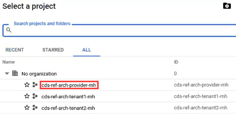
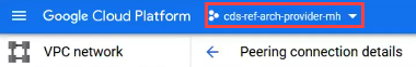
- Log into the Google Cloud console and click “Select a project” dropdown.

- On the “Select a project” box, click the link for the name of the provider project.
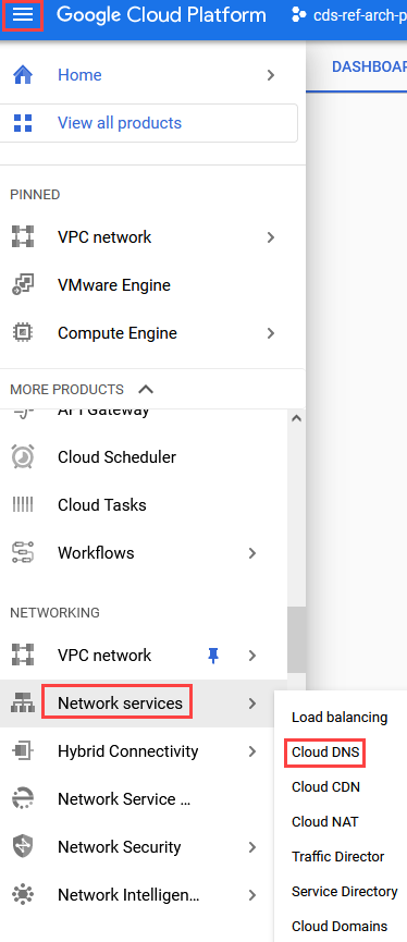
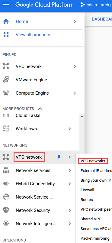
- In the top left pane, click the three horizontal bars and navigate down to Network -> Network Services -> and click Cloud DNS.
-
If prompted to enable the API first, click Enable API.
-
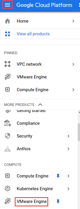
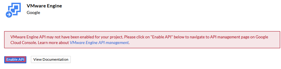
In the top left pane, click the three horizontal bars and navigate down to Compute -> and select VMware Engine. Note that this will open a second browser tab, keep both tabs open for easier navigating when configuring later.
- Click Enable API.
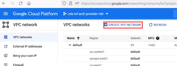
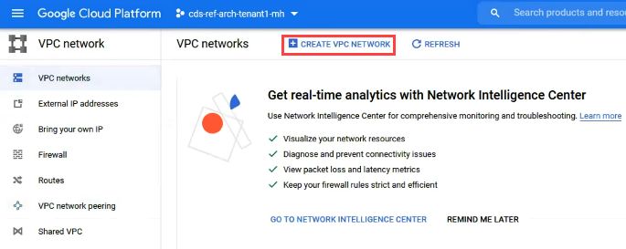
- In the top left pane click the three horizontal bars and navigate to Networking -> VPC Network -> and select VPC Networks.
- Click CREATE VPC NETWORK.
-
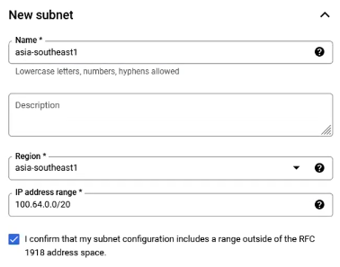
Enter in the following:
-
Name: Subnet name such as the region the environment is in such as “asia-southeast1”
-
Region: Select the region the environment is in to host the subnet such as “asia-southeast1”
-
IP Address Range: Provide a range such as 100.64.0.0/20
-
Check the box for “I confirm that my subnet configuration includes a range outside of the RFC 1918 address space”
-
Private Google Access: Select the ON radial button
-
-
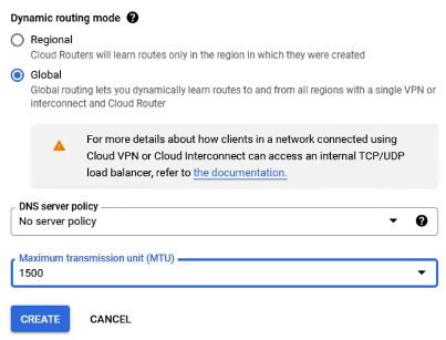
Under Dynamic Routing Mode:
-
Select Global
-
Set the Maximum MTU to 1500
-
Click Create
-
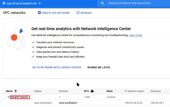
- Once the task has completed, scroll to the bottom of the page, and click the name of the provider management network that was just created.

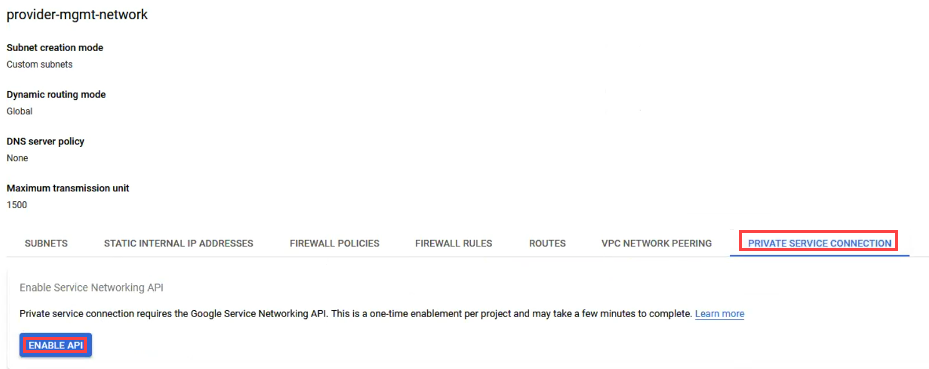
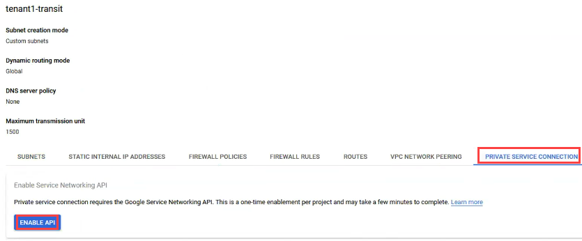
- In the VPC network details screen, click the PRIVATE SERVICE CONNECTION tab and click the Enable API Button.
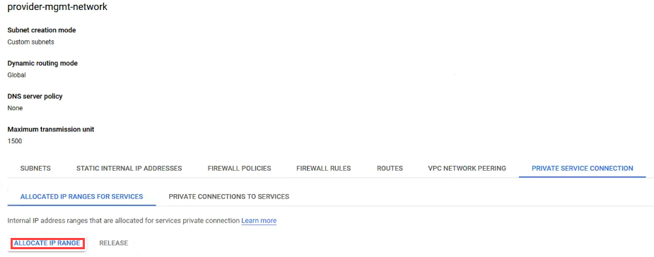
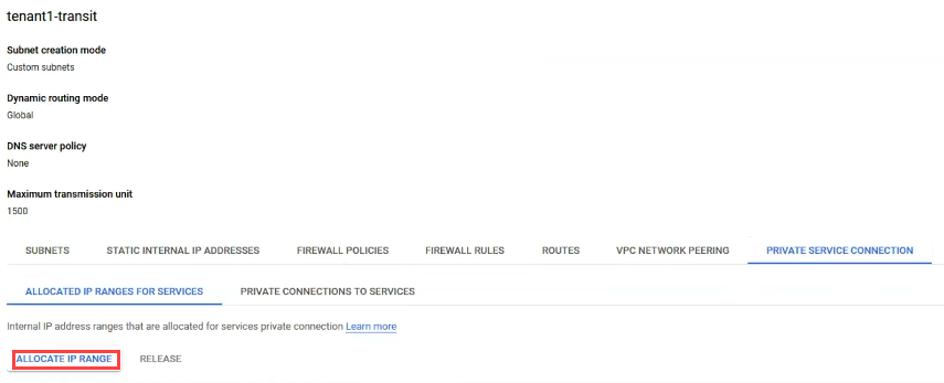
- Once enabled, click ALLOCATE IP RANGE.
-
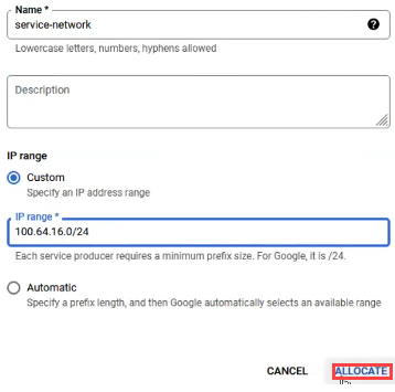
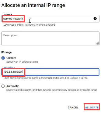
For Allocate an internal IP range enter:
-
Name: service-network
-
IP Range: The next subnet available in the provider range previously entered, 100.64.16.0/24 in this case
-
Click ALLOCATE
-
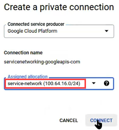
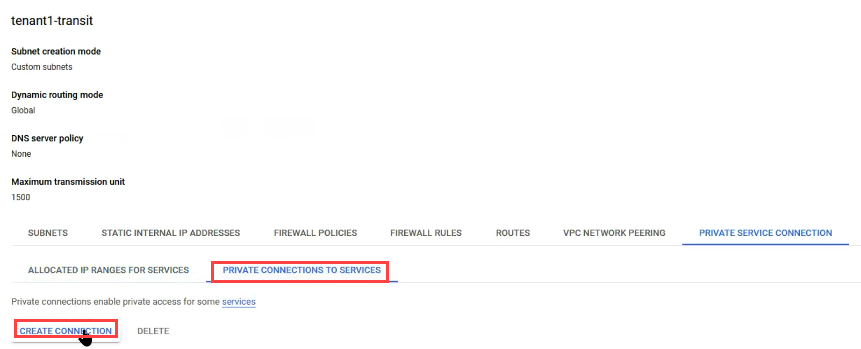
- Click the PRIVATE CONNECTIONS TO SERVICES tab and click CREATE CONNECTION.
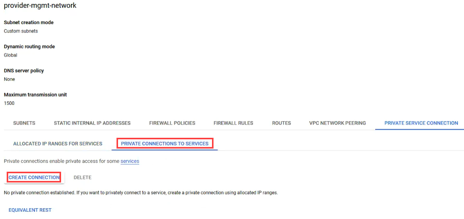
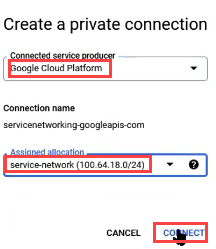
- On the private connection screen, ensure Google Cloud Platform is selected and select the service-network that was created under Assigned Allocation and click Connect.
Create and Configure the Software Defined Data Center #
The following section describes the steps required to setup the Software Defined Data Center (SDDC) that tenants will consume for resources.
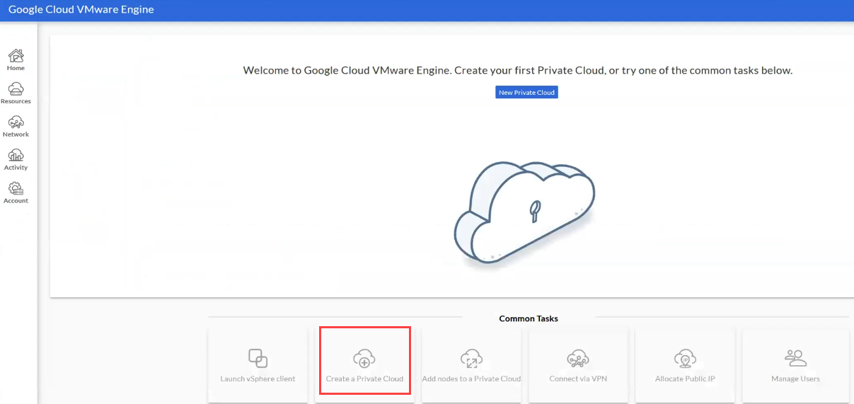
- Go to the browser tab that has GCVE open and click Create a Private Cloud.
-
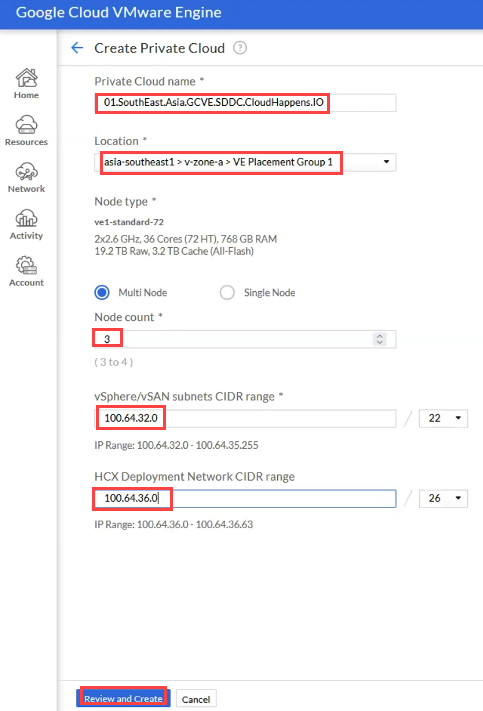
Enter the following information:
-
Private Cloud Name: Name of the SDDC to create
-
Location: The GCP data center to create the SDDC
-
Node Type: Multi Node for production deployments
-
Node Count: Number of nodes to initially use for the SDDC (4 minimum)
-
vSphere/vSAN Range: IP range to use for vSphere and vSAN
-
HCX Deployment Range: IP range to use for HCX (while the input is required, using HCX is not required)
-
Click Review and Create when ready
-
Click Create
-
The SDDC creation process takes around one hour to complete.
-
-
Once the SDDC completion process works, the next steps are completed most easily by have two browser tabs open: one for the GCVE environment and one on the provider project settings.
-
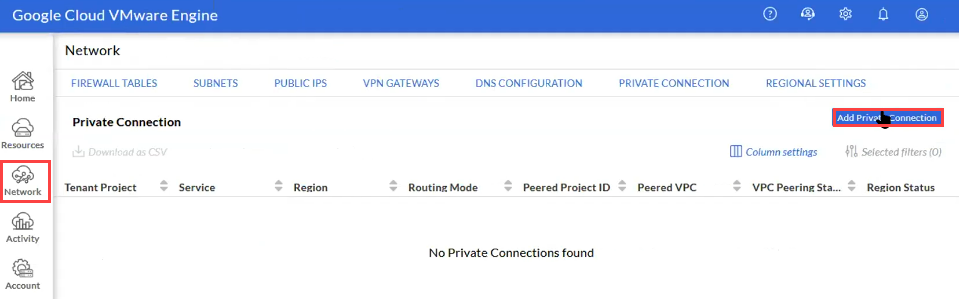
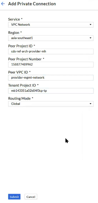
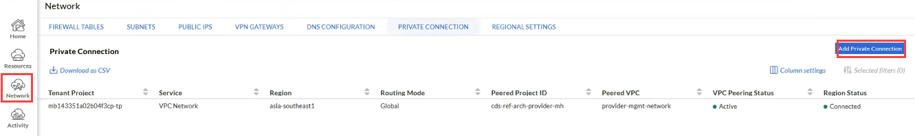
On the browser tab with GCVE, in the left pane click Network and in the right pane click Add Private Connection.
-
Enter the following information:
-
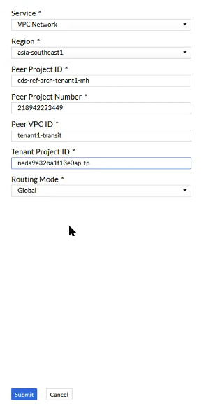
Service: VPC Network
-
Region: The region the SDDC was created in
-
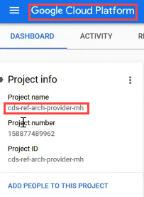
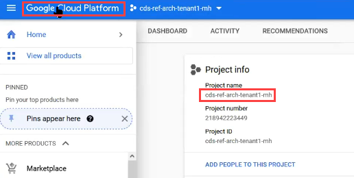
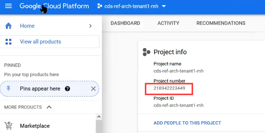
Peer Project ID: this will be the provider project name, which can be found in the browser tab with the provider project by clicking Google Cloud Platform and then copying the Project Name field and pasting it into the Peer Project ID field
-
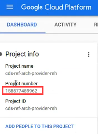
- Peer Project Number: This is the project ID, which can be found in the tab where the Project Name filed is immediately under that; copy and paste the value into the Peer Project Number field
-
Peer VPC ID: This will be “provider-mgmt-network” unless it was named differently. If it was name differently, enter the name used.
-
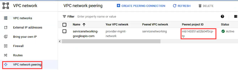
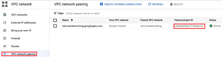
Tenant Project ID: To get the tenant project ID value, on the browser tab with the provider project, in the left pane click VPC Network -> VPC Network Peering and in the right pane, copy the value for Peered Project ID and paste it into this field.
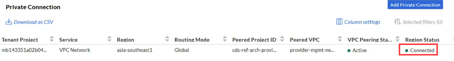
- Verify the Routing Mode is set to Global and click Submit.
- After about 5 minutes, the Region Status should show Connected.
- Navigate back to VPC Network -> VPC Networks -> and click on the provider-mgmt-network.
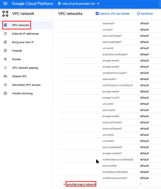
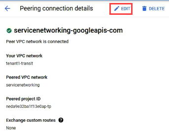
- Click on the VPC NETWORK PEERING tab and click into the servicenetworking name.
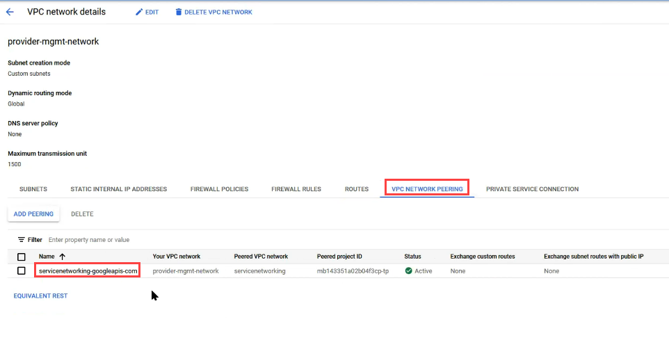
- Click on EDIT.
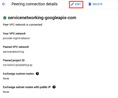
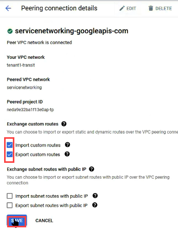
- Under Exchange Custom Routes, check the boxes for Import Custom Routes and Export Custom Routes and click SAVE.
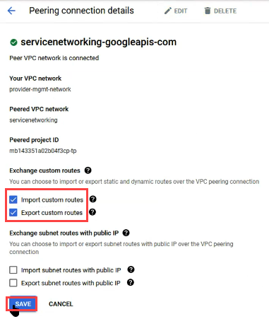
- After saving, the route Status should all change to a Status of accepted.
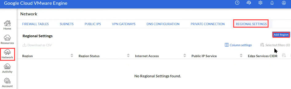
- On the GCVE browser tab, click Network in the left pane and then in the right pane click the REGIONAL SETTINGS tab and click Add Region.
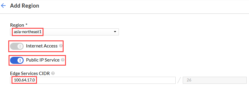
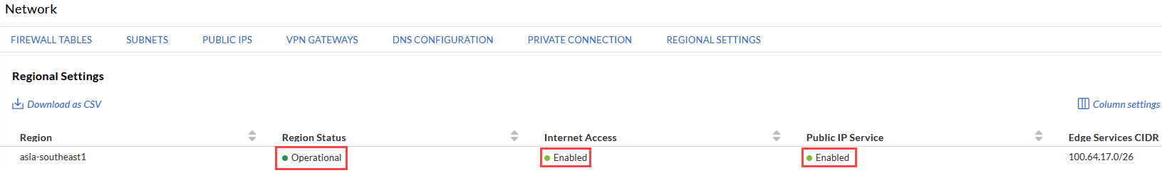
- On the Add Region screen, select the Region the SDDC is in, enable Internet Access and Public IP Service, and use the next provider CIDR block for the Edge Services CIDR and click Submit. After a few minutes, it should show that the status is Operational and Enabled.
Setup the Tenant Projects #
The following steps describes the steps required to configure the tenant projects. Many of the steps are the same done in the provider tenant in creating a tenant service network and peering projects.
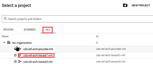
- In the Google Cloud Portal, click the project name dropdown beside Google Cloud Platform.
- On the Select a project screen, click the ALL tab and select the tenant project.
- In the top left pane click the three horizontal bars and navigate to VPC Network -> VPC Networks -> and click the Default network name.
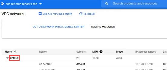
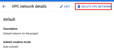
- Click DELETE VPC NETWORK.
-
Click DELETE when prompted to confirm
-
Click CREATE VPC NETWORK.
-
Enter the following:
-
Name: Name for the network such as “tenantname-transit”
-
New Subnet Name: Name to match the region such as asia-southeast1
-
Region: The region the SDDC is in
-
IP Address Range: A CIDR range out of the next available range. Check the box for “I confirm the subnet configuration includes a range outside the RFC 1918 address space”
-
Private Google Access: Turn On
-
Click Done on the Subnet Section
-
Dynamic Routing Mode: Global
-
MTU: 1500
-
Click CREATE
-
-
Once the network creation has completed, click into the network name.
- Click the PRIVATE SERVICE CONNECTION tab and then click ENABLE API.
- Once completed, click ALLOCATE IP RANGE.
-
Set the following:
-
Name: service-network
-
IP Range Custom: Next available CIDR range
-
Click Allocate
-
- Click the PRIVATE CONNECTIONS TO SERVICES tab and then click CREATE CONNECTION.
- On the private connection screen, ensure Google Cloud Platform is selected and for Assigned Allocation, select the service-network that was just created and click CONNECT.
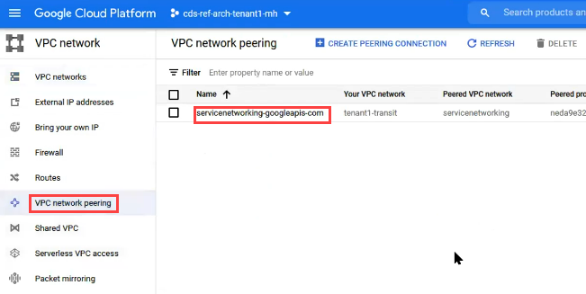
- In the left pane click on VPC Network Peering and in the right pane click into the servicenetworking name.
- Click EDIT.
- Under Exchange Custom Routes, check the boxes for Import Custom Routes and Export Custom Routes and click SAVE.
- Navigate to the GCVE page and in the left pane click Network and in the right pane click Add Private Connection.
-
Enter the following information:
-
Service: VPC Network
-
Region: Region the SDDC is in
-
Peer Project ID: this will be the provider project name, which can be found in the browser tab with the provider project by clicking Google Cloud Platform and then copying the Project Name field and pasting it into the Peer Project ID field
-
- Peer Project Number: This is the project ID, which can be found in the tab where the Project Name filed is immediately under that; copy and paste the value into the Peer Project Number field
-
Peer VPC ID: This will be “tenantname-transit” unless it was named differently. If it was name differently, enter the name used.
-
Tenant Project ID: To get the tenant project ID value, on the browser tab with the provider project, in the left pane click VPC Network -> VPC Network Peering and in the right pane, copy the value for Peered Project ID and paste it into this field.
- Verify the Routing Mode is set to Global and click Submit.
-
After about 5 minutes the Region status should show Connected.
-
Repeat the previous steps for configure each tenant project.
Create a Jumphost in the Provider Project and Allow Network Access #
The following section describes the steps required to create a jumphost in the provider project to use for vCenter and NSX access as well as other potential tasks made easier with local access.
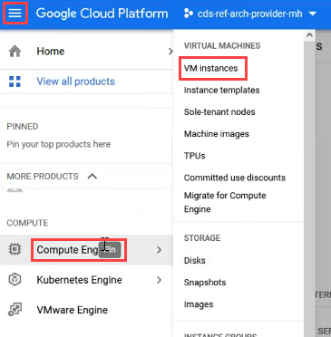
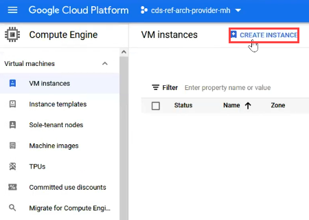
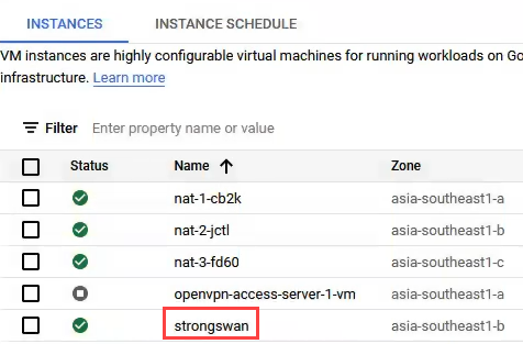
- In a browser navigate to the provider project as previously described and in the top right pane click the three horizontal bars and select Compute Engine -> VM Instances.
- Click CREATE INSTANCE.
-
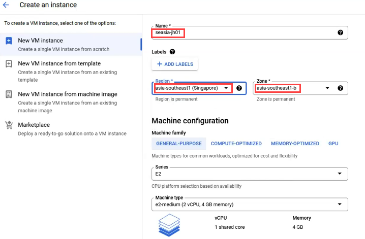
Enter the following information:
-
Name: A name for the VM to help the region and function
-
Region: Same region as the SDDC
-
Zone: Zone in the region of the SDDC
-
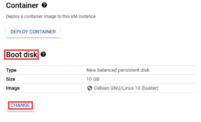
- Scroll down to the Boot Disk section and click CHANGE
-
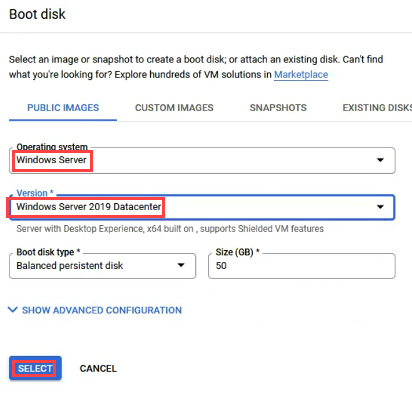
Change the following:
-
Operating System: Windows Server
-
Version: Select a current version, such as 2019 Datacenter
-
Size: Change the default size if desired
-
Click SELECT
-
- Scroll down and expand NETWORKING, DISKS, SECURITY, MANGEMENT, SOLE-TENANCY
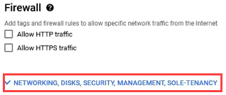
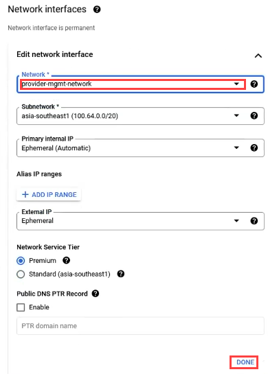
- Under “Edit network interface”, click the Network drop down and select the provider-mgmt-network that was previously created and then click DONE< then click CREATE
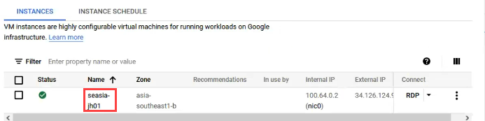
- After several minutes the jumphost should show ready; click on the name of it to open the settings.
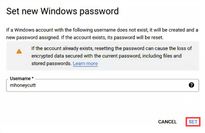
- Click SET WINDOWS PASSWORD
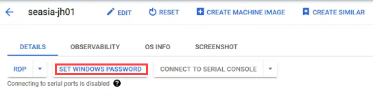
- On the pop-up screen, it will fill in the Username of the person logged in, click SET to set the password.
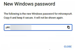
- After a few moments it will display the password that is set. Copy the password and then click CLOSE.
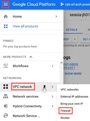
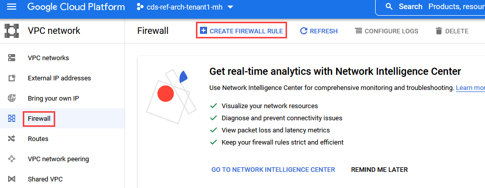
- Allow access through the firewall by clicking the three horizontal bars in the top left and select VPC Network -> Firewall.
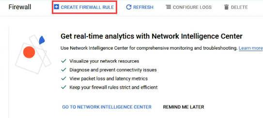
- Click CREATE FIREWALL RULE.
-
Set the following for the firewall rule:
-
Name: Name stating the service provided such as “rdp-in”
-
Network: The provider-mgmt-network that was created previously
-
Direction of Traffic: Ingress
-
Targets: All instances in the network
-
Source IPv4 ranges: 0.0.0.0/0
-
Protocols and ports: TCP 3389
-
Click CREATE
-
-
Click CREATE FIREWALL RULE again
-
Set the following for the firewall rule:
-
Name: This will be for east-west connectivity, so name it to identify what it is such as “ew” or “east-west”
-
Network: The provider-mgmt-network that was created previously
-
Direction of Traffic: Egress
-
Targets: All instances in the network
-
Source IPv4 ranges: The range of the management network, such as 100.64.0.0/16
-
Protocols and ports: Allow all
-
Click CREATE
-
-
On the settings of the jumphost that was created, copy the External IP to use in RDP.
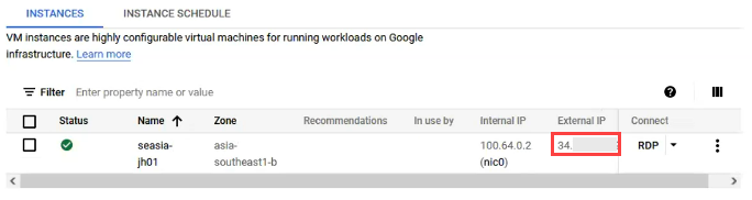
- Log into the jumphost with the external IP and the credentials previously created to verify access.
Prepare for and Deploy the Reverse Proxy #
The following section describes the steps required to prepare the environment for the proxy, generate it, and then deploy and associate the proxy to the SDDC that was created.
Create the CDs Instance (If not already created) #
The following steps describes the steps required to create a CDs instance if one does not already exist that the SDDC should be associated to.
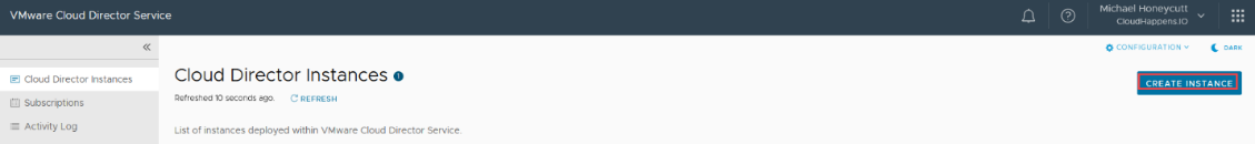
- In Partner Navigator, navigate to VMware Cloud Director service and click CREATE INSTANCE.
- Enter the required information and click CREATE INSTANCE.
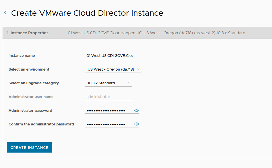
- The CDs instance will take around 30 minutes to complete.
Generate the Proxy #
The following steps describes the steps required to generate the proxy that will be used for the connection from CDs to the SDDC. These steps are completed from the partner navigator portal and require the CDs instance to already exist.
-
On the GCP provider based jumphost, log into Partner Navigator, navigate to VMware Cloud Director service.
-
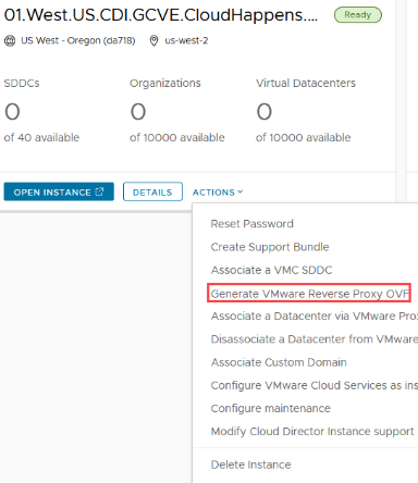
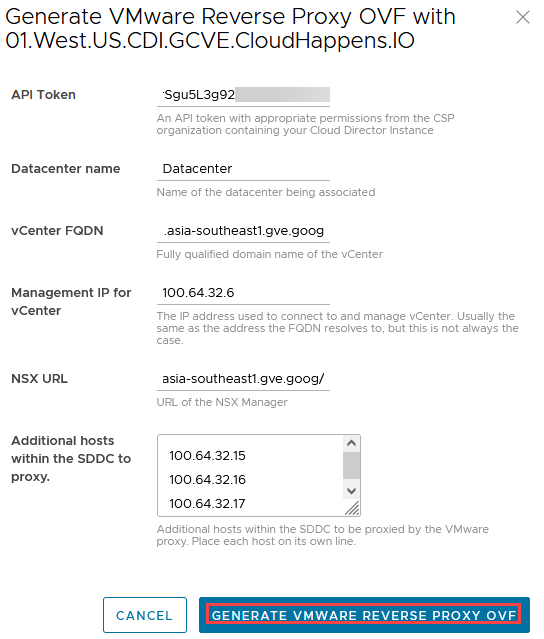
On the CDs instance to associate the SDDC to click Actions and select Generate VMware Reverse Proxy OVF.
-
Enter the following:
-
API Token: API token from your account in Partner Navigator
-
Datacenter Name: Datacenter
-
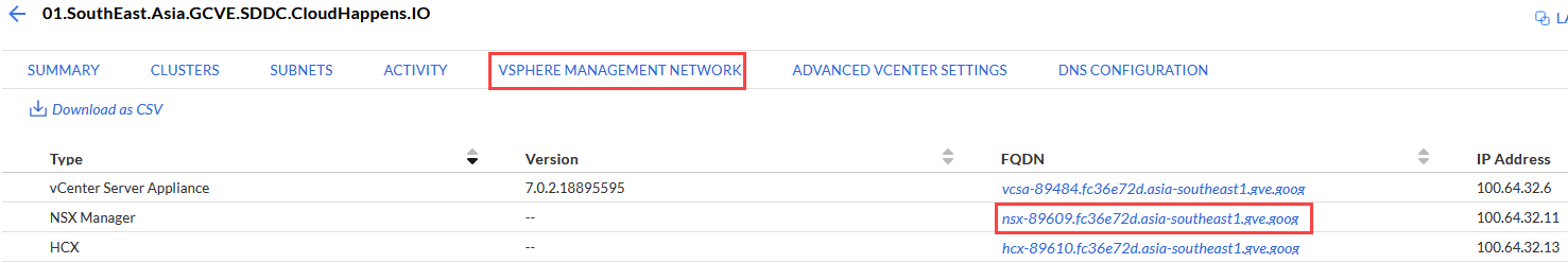
vCenter FQDN: The FQDN of the VCSA appliance under Google Cloud VMware Engine -> Resources -> VSHPERE MANAGEMENT NETWORK
-
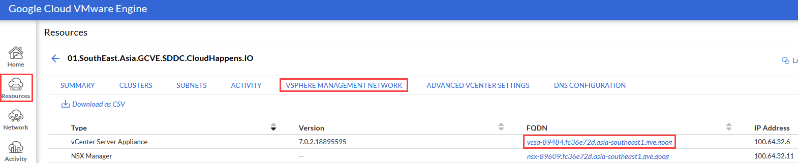
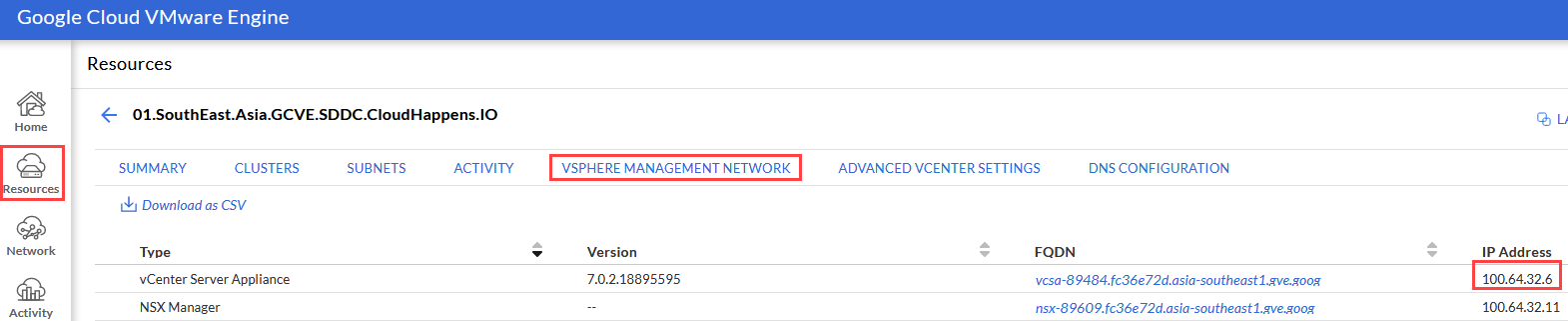
- Management IP for vCenter: The IP address of the VCSA appliance
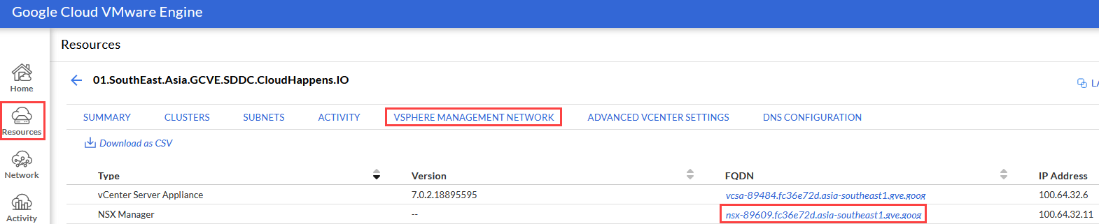
- NSX URL: URL of the NSX manager
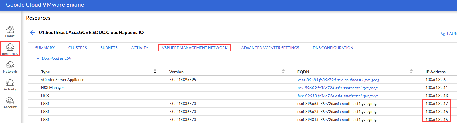
- Additional hosts within the SDDC to proxy: The IP address of the ESXi hosts that are part of the SDDC. Note that each IP MUST be on a separate line
- Once the information has been entered, click GENERATE VMWARE REVERSE PROXY OVF
-
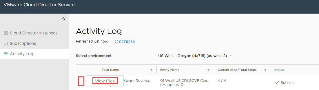
The Activity Log on the CDs instance can be monitored for the status of the task. Skip ahead to Prepare the Environment for the Proxy if desired to complete those steps while waiting for the proxy to generate.
-
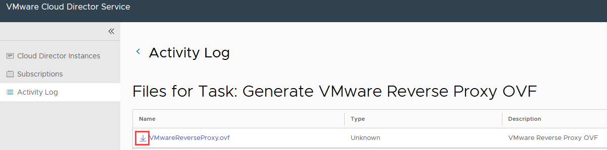
Once the task has completed, click the three horizontal dots, and select View Files.
- Click the down arrow icon to download the OVF file to the provider jumphost locally.
Prepare the Environment for the Proxy #
Before deploying the proxy, a network segment must be created and DHCP setup so that it can get an IP address. The following steps describe how to create the segment and configure DHCP.
- On the GCVE page in the Google Cloud Portal, click Resource in the left pane and click the name of the SDDC.
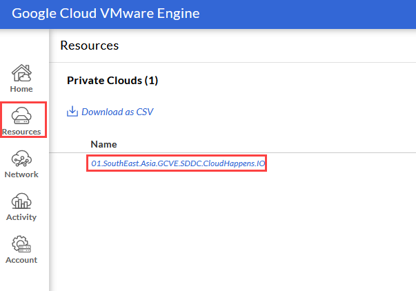
- Click on VSPHERE MANAGEMENT NETWORK tab and in the right click the NSX Manager FQDN and copy the link location.
-
RDP to the jumphost that was created on the provider network previously, open a browser and navigate to the FQDN of the NSX manager from the link that was copied.
-
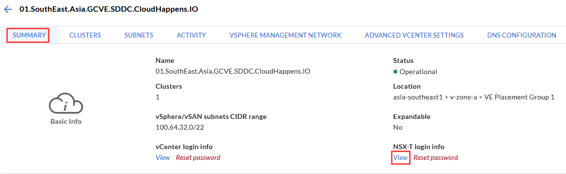
Back on the GCVE browser, click the SUMMARY tab and then in the NSX-T Login Info section, click View.
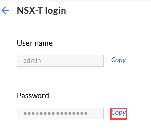
- In the Password section, click Copy.
-
Log into the NSX-T manager URL as admin with the password that was coped.
-
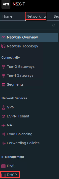
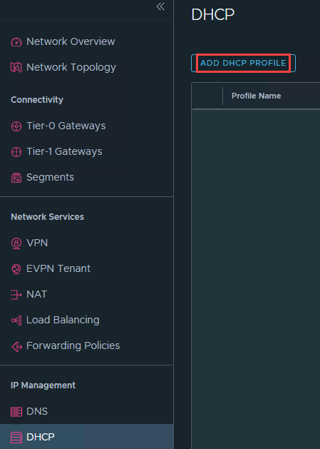
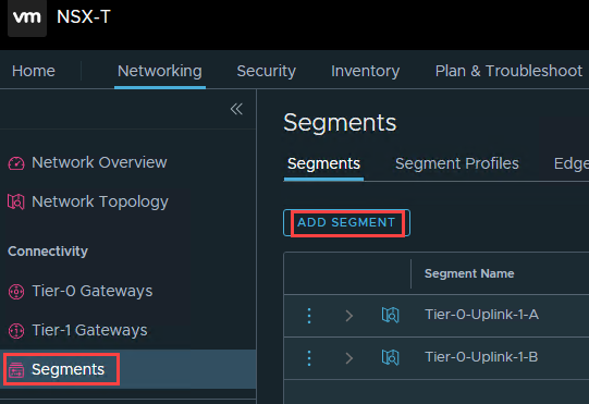
In the NSX-T manager UI, click the Networking tab in the left pane click DHCP.
- Click ADD DHCP PROFILE.
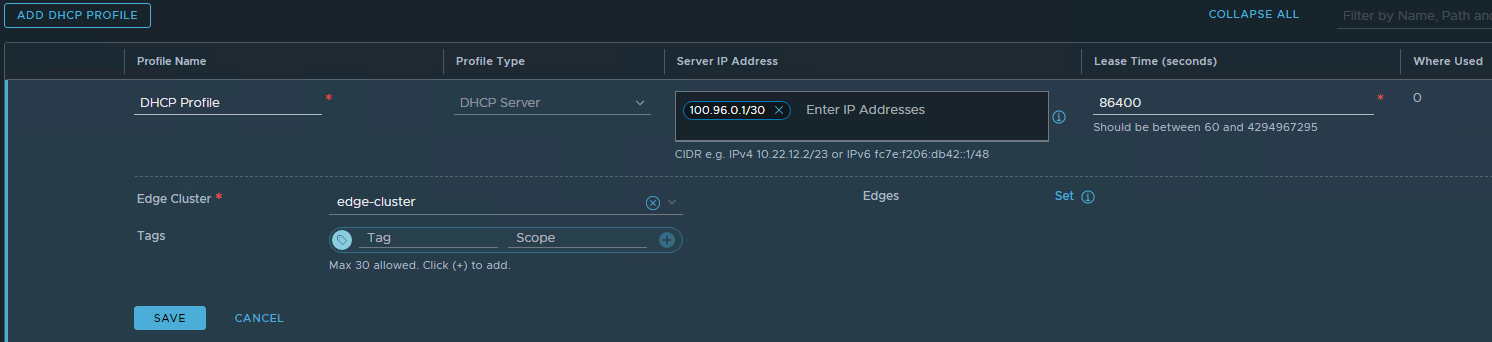
-
Enter the following:
-
Profile Name: A name for the DHCP profile
-
Profile Type: DHCP Server
-
Server IP Address: A CIDR subnet for the scope
-
Edge Cluster: The edge cluster that was created
-
Click SAVE
-
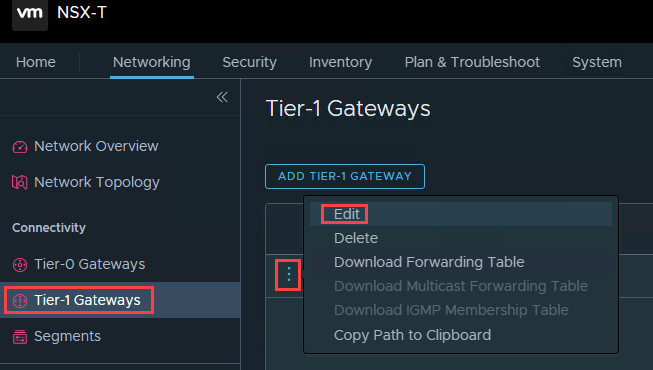
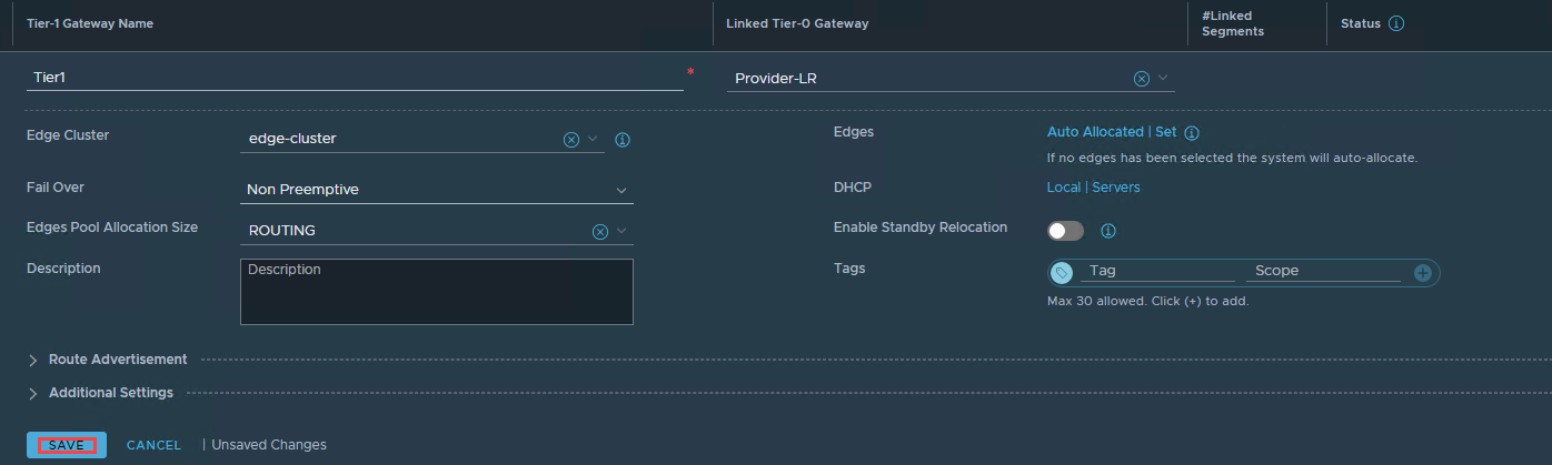
- In the left pane click Tier-1 Gateways and in the right pane beside Tier1, click the three vertical dots and select Edit.
- Click Set DHCP Configuration.
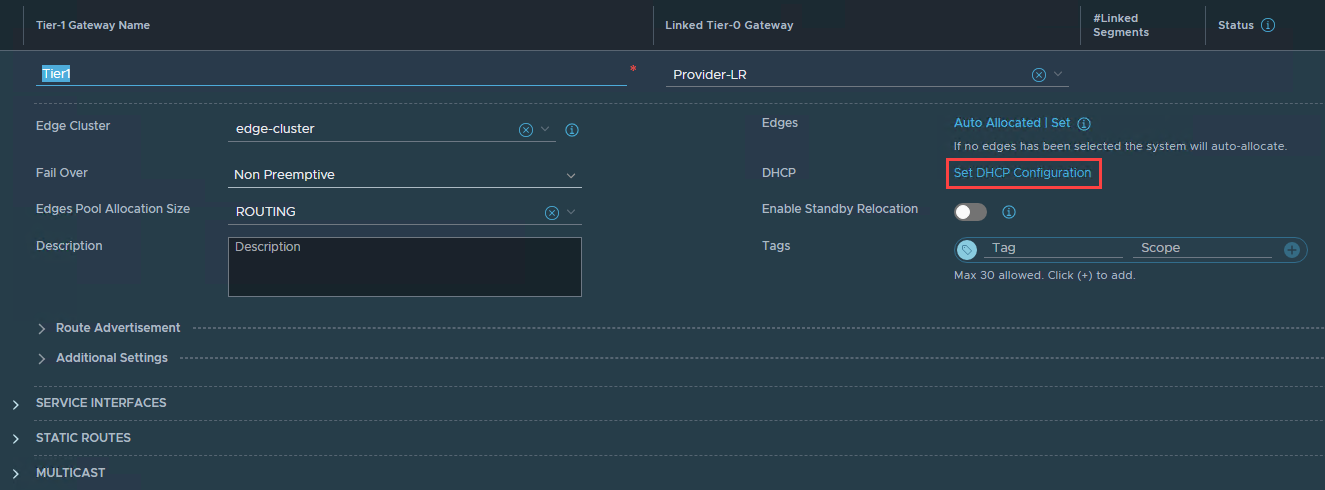
- For Type select DHCP Server and for DHCP Server Profile select the DHCP Profile that was created and click SAVE.
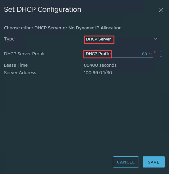
- Click SAVE.
- In the left pane click Segments, then click ADD SEGMENT.
-
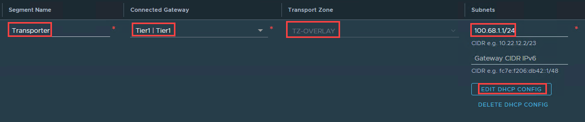
Enter the following:
-
Segment Name: Proxy
-
Connected Gateway: Tier1 | Tier1
-
Transport Zone: TZ-Overlay
-
Subnet: The subnet CIDR
-
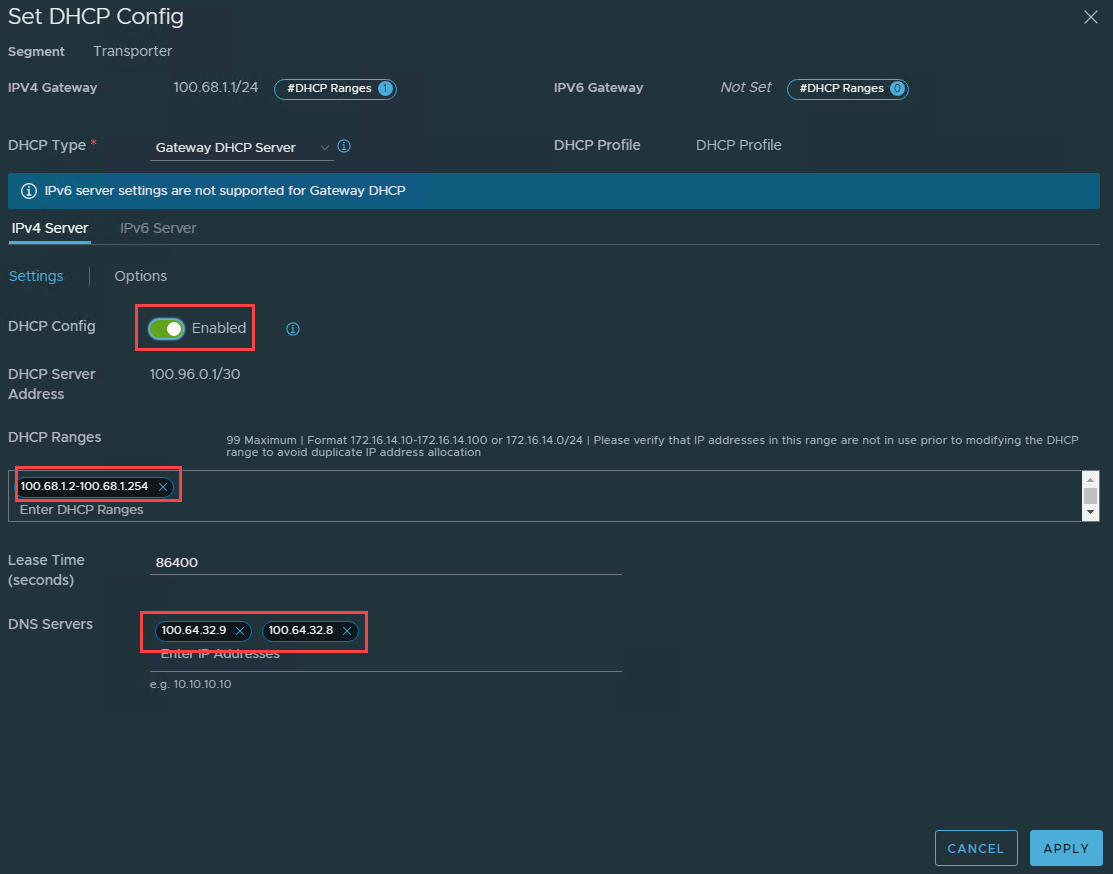
Click EDIT DHCP CONFIG
-
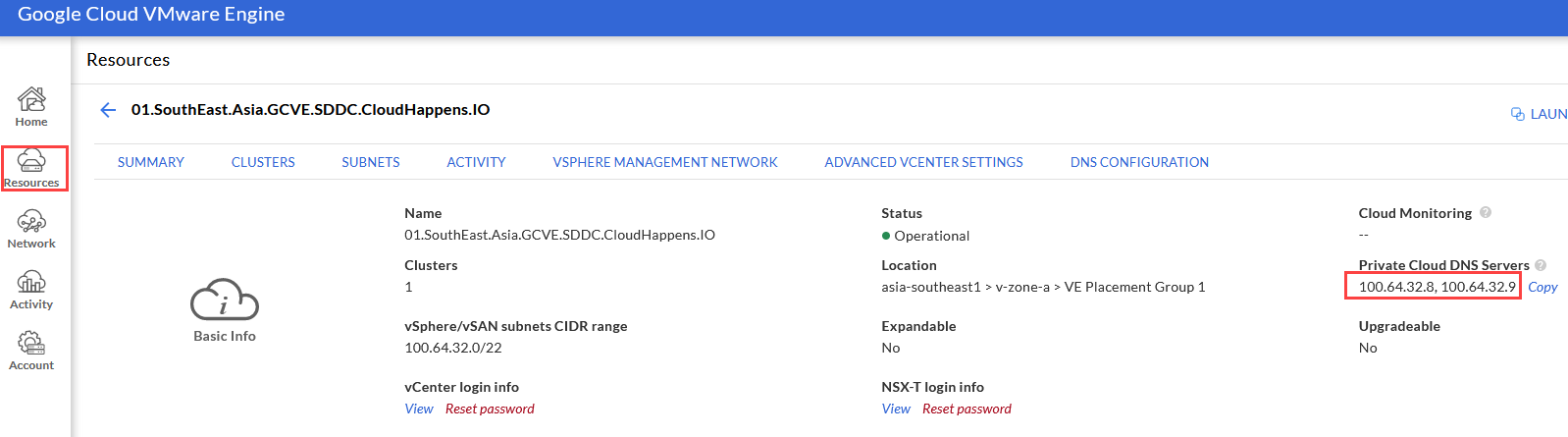
- Check the DHCP Config enabled, set a DHCP range, enter the DNS servers from GCVE, and then click APPLY (the DNS servers can be found on the GCVE page, clicking Resources in the left tab and then clicking the name of the SDDC, and on the SUMMARY tab under Private Cloud DNS Servers.
Deploy and Connect the Proxy #
The following steps describes the steps required to deploy the proxy and associate it to the CDs instance in Partner Navigator.
-
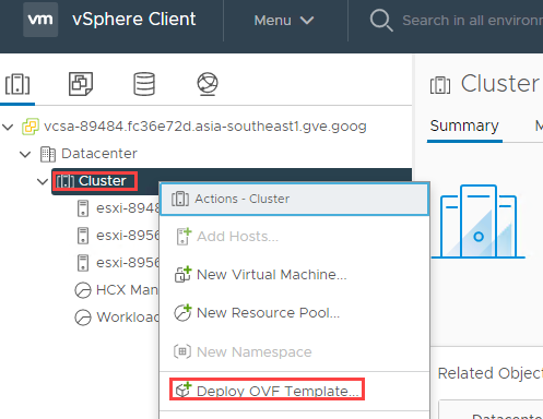
On the GCP provider based jumphost, open a browser to the vCenter UI.
-
Right click Cluster and select Deploy OVF Template.
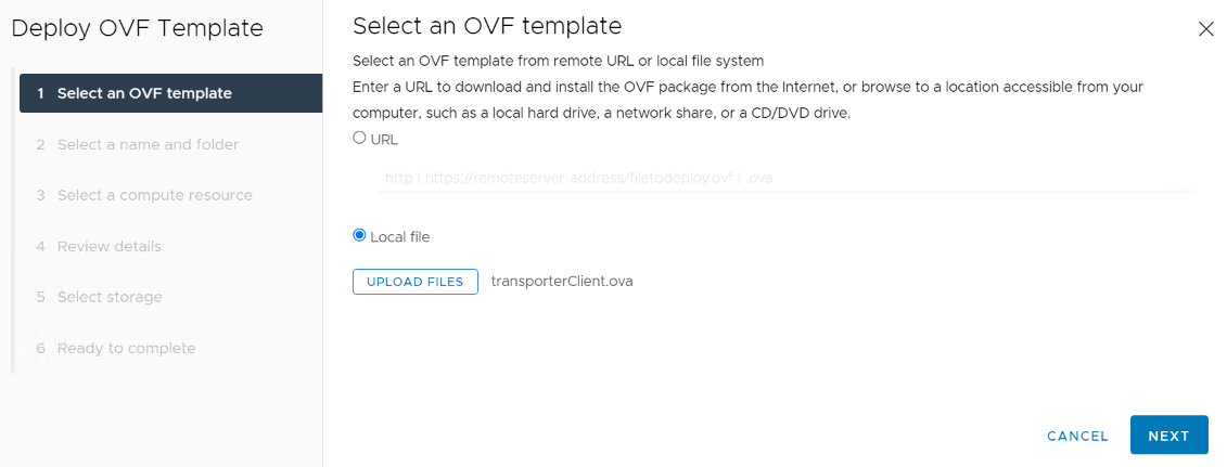
- Select Local File and navigate to the reverse proxy OVF that was downloaded, select it and click NEXT.
- Provide a virtual machine name and click NEXT.
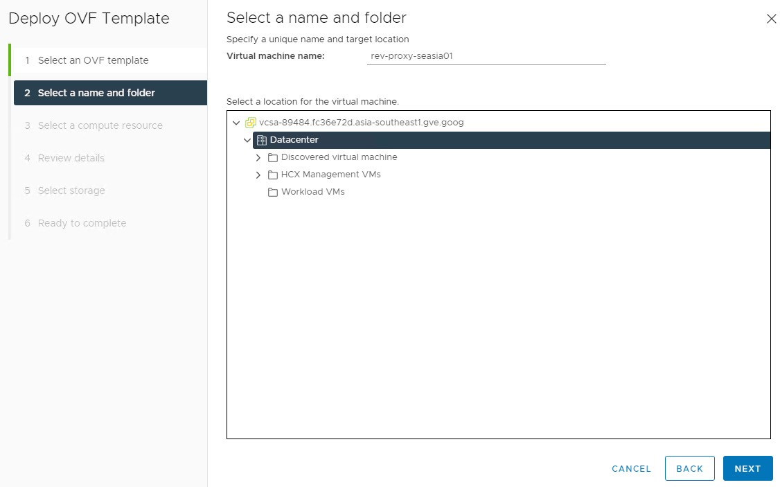
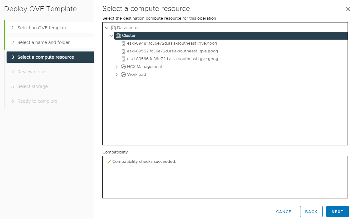
- Select the Cluster name and click NEXT.
-
Click Next.
-
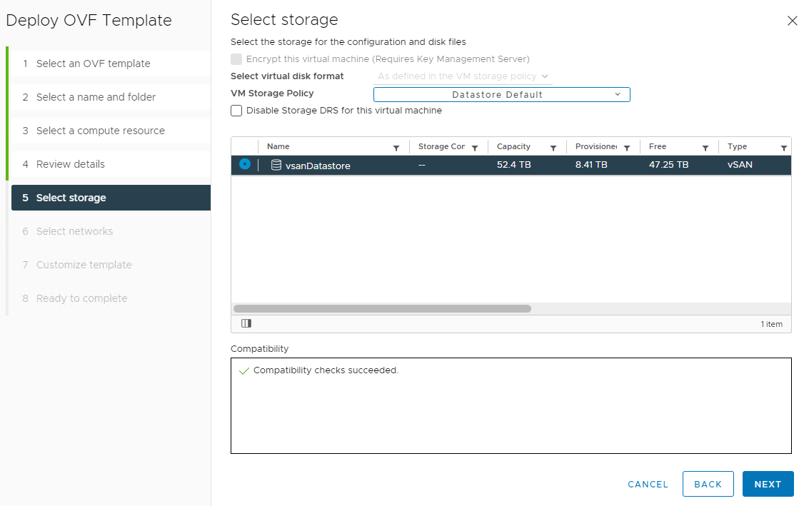
Select the vsanDatastore and click NEXT.
-
Select the Proxy network that was previously created and click NEXT.
-
On the Customize Template page, copy and save the root password and click NEXT.
-
Click FINISH to being the deployment.
-
After deployment, power on the appliance.
-
Log into the proxy appliance and verify it has an IP address by running “ip a”.
-
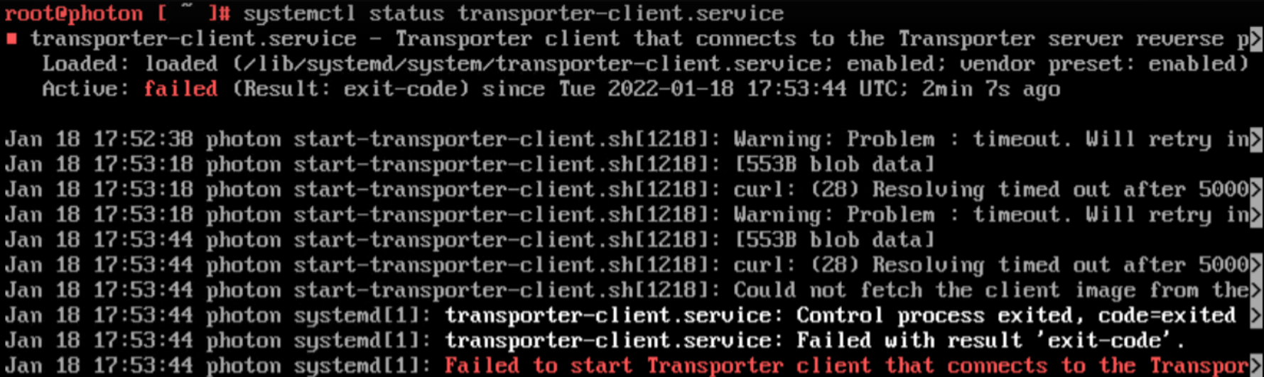
Run the command “systemctl status transporter-client.service” and ensure it shows running.
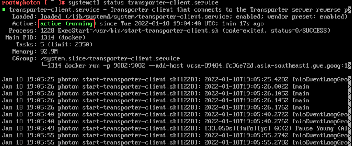
- If the transporter-client.service is showing an error, verify that DNS resolution is working properly and that it can access the Internet. The below screenshot shows an error when DNS is not working.
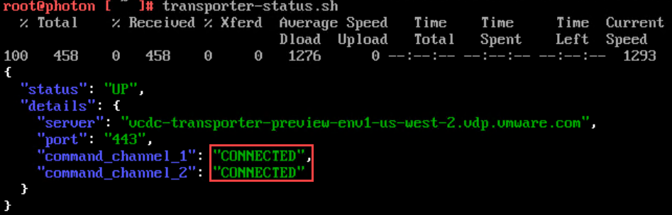
- Run the command “transporter-status.sh” and verify it shows connected.
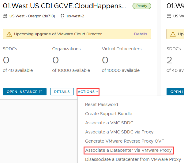
- In Partner Navigator, go to the CDs instance the proxy was generated from and click Actions -> Associate a Datacenter via VMware Proxy.
-
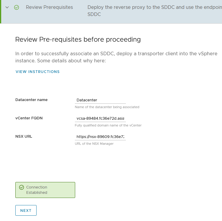
Enter the following:
-
Datacenter name: Datacenter
-
vCenter FQDN: VCSA FQDN that was used to generate the proxy
-
NSX URL: URL of NSX manager that was used to generate the proxy
-
It will attempt an initial connection to the proxy and if it connects, it will display Connection Established
-
-
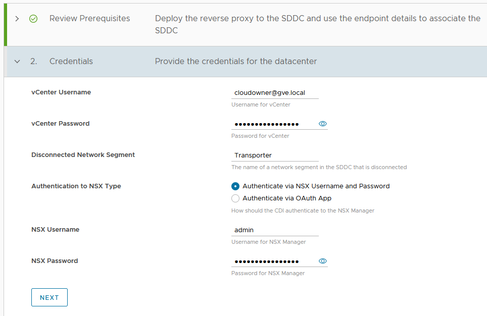
On the Credentials page, enter the following:
-
vCenter Username: cloudowner@gve.local
-
vCenter Password: The password for the supplied username
-
Disconnected Network Segment: Enter the name of the network the proxy is on (Proxy)
-
Authentication to NSX Type: Authenticate via NSX Username and Password
-
NSX Username: admin
-
NSX Password: The password for NSX admin account
-
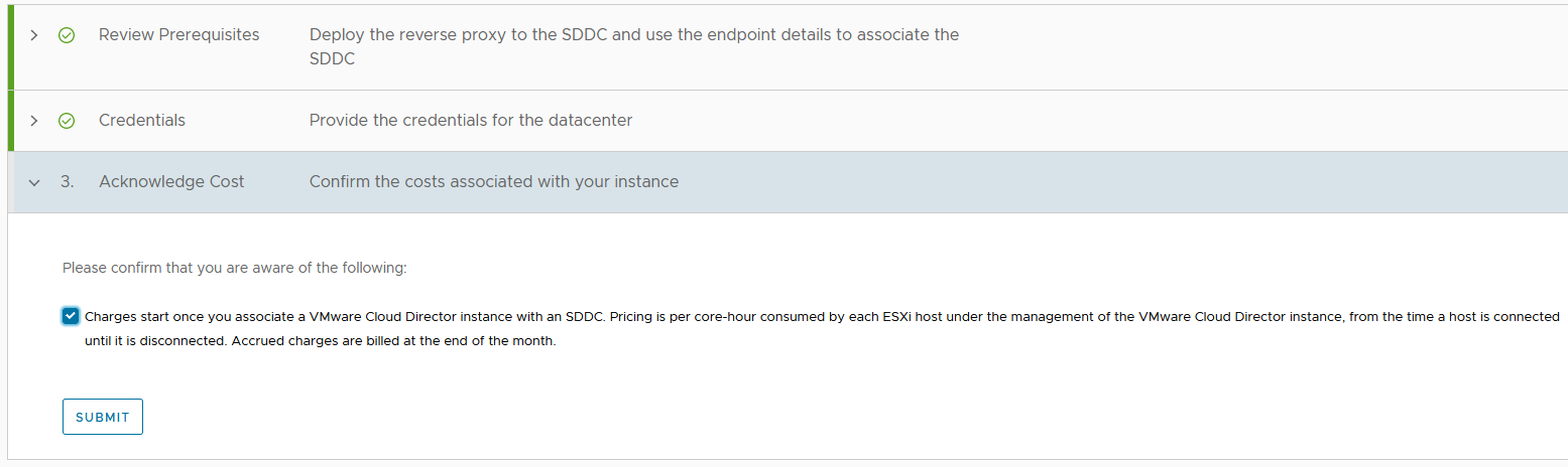
- Check the box to acknowledge charges will begin and click SUBMIT.
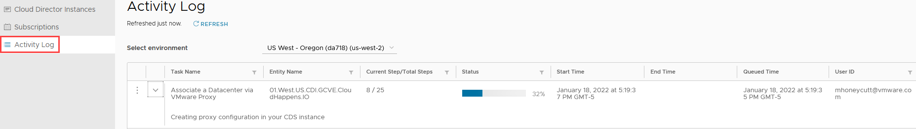
- The Activity Log on the CDs instance can be monitored for the status of the association task.
-
It should take about 5 to 10 minutes for the task to completed.
-
Once the task has finished, it can take up to 4 hours to show up as an associated SDDC in the CDs instance. Opening the VCD instance to bring up the UI should show the SDDC as a PVCD that can be used to create VDCs for tenants; you do not have to wait for it to show up as associated in the Partner Navigator portal.
Deploy and Configure IPsec Tunnel #
The following section describes the steps required to deploy and configure a StrongSwan VPN appliance in the tenant’s project to connect to their T1 in the SDDC that was deployed via an IPsec tunnel. This is merely a demonstration of how to deploy a VPN appliance and any suitable appliance can be used.
The steps below are based on CentOS 7 as the operating system; using another flavor of Linux may result in different steps or actions required to get it to work properly.
The default routes to the Internet will use instance tags to keep from the routes leaking back into the GCVE environment. This tag can be whatever the provider desires, but it must be uniform across all routes that point to the Internet and be applied to any VM that will need to be access to/from to the Internet in the provider owned customer project.
Deploy a Linux Instance and Configure StrongSwan #
The following steps describes the steps required to deploy a virtual machine, install StrongSwan and configure it for an IPSec tunnel connection to a tenant T1.
- First create a firewall rule in the tenant project by going to VPC Network -> Firewall and click CREATE FIREWALL RULE.
-
Enter the following:
-
Name: gcve-transit
-
Network: tenatname-transit
-
Priority: 100
-
Direction of Traffic: Ingress
-
Action on match: Allow
-
Targets: All instances in the network
-
Source IPv4 Ranges: Range for transit network – such as 100.64.0.0/16
-
Protocols and ports: Allow all
-
Click Save
-
-
Click CREATE FIREWALL RULE again and enter the following:
-
Name: ipsec-egress
-
Network: tenatname-transit
-
Priority: 100
-
Direction of Traffic: Egress
-
Action on match: Allow
-
Targets: All instances in the network
-
Destination IPv4 Ranges: Range for transit network – such as 100.64.0.0/16
-
Protocols and ports: IPsec Ports
-
Click Save
-
-
Create a new instance in the tenant and set:
-
Boot Disk: Change to CentOS 7
-
Expand NETWORKING, DISKS, SECRUITY, MANGEMENT, SOLE-TENANCY
-
IP Forwarding: Check the box to Enable
-
Ensure the network interface is on the “tenantname-transit” network
-
Click CREATE
-
-
-
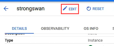
Once completed, click on the name of the instance to bring up its settings.
-
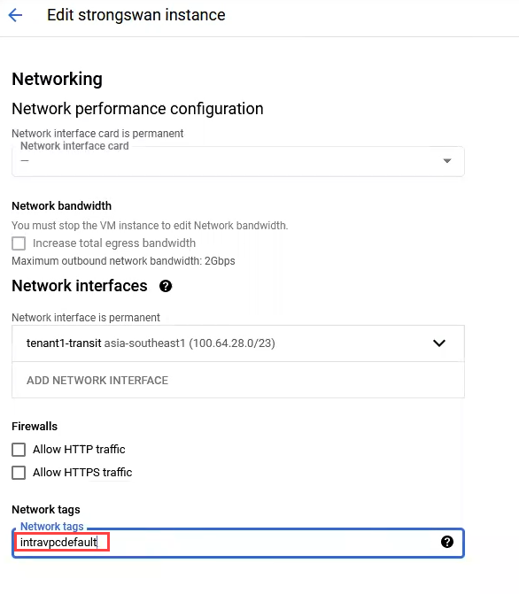
At the top of the screen, click EDIT.
-
Scroll down and in the Network Tags box, put the network tag name, then save the settings.
-
Under the Connect column click SSH to connect to it.
-
Run sudo su and then run “yum install strongswan -y” to install strongswan.
-
Copy the command below and paste into the shell with ctrl v
cat >> /etc/sysctl.conf << EOF
net.ipv4.ip_forward = 1
net.ipv4.conf.all.accept_redirects = 0
net.ipv4.conf.all.send_redirects = 0
EOF
-
Run the command sysctl -p
-
CD to /etc/strongswan/swanctl/conf.d and run vi nsxt.conf.
- Enter the following information in the nsxt.conf file replacing localAddr with the local IP of the tunnel, remoteAddr with the remote IP of the tunnel, remoteTS with the network CIDR of the remote end of the tunnel, and PresharedKey with the secret used for the tunnel.
connections {
gw-gw {
local_addrs = localAddr
remote_addrs = remoteAddr
local {
auth = psk
id = localAddr
}
remote {
auth = psk
id = remoteAddr
}
children {
net-net {
local_ts = 0.0.0.0/0
remote_ts = remoteTS
start_action = start
updown = /usr/local/libexec/ipsec/_updown iptables
esp_proposals = aes128gcm128-modp2048
}
}
version = 2
proposals = aes128-sha256-modp2048
}
}
secrets {
ike-1 {
id-1 = localAddr
secret = PresharedKey
}
ike-2 {
id-2 = remoteAddr
secret = PresharedKey
}
ike-3 {
id-3a = localAddr
id-3b = remoteAddr
secret = PresharedKey
}
ike-4 {
secret = PresharedKey
}
ike-5 {
id-5 = localAddr
secret = PresharedKey
}
}
-
Run the command swanctl --load-all
-
CD to /etc and run “vi ipsec.secrets”
- Enter the following line, replacing the words with their values: localTunnelIP remoteTunnelIP : PSK ‘PresharedKey" and save the file.

-
Run the command sudo strongswan restart
-
Run the command yum install iptables-services and once installed run systemctl start iptables
-
Add the following iptables rules in to allow traffic to be forwarded. Any line that contains remoteNet should have that replaced with the CIDR of the remote network in GCVE. Note that each line must be copied and pasted into the SSH session on the VPN server one by one.
iptables -A INPUT -i eth0 -p esp -j ACCEPT
iptables -A INPUT -i eth0 -p ah -j ACCEPT
iptables -A INPUT -i eth0 -p udp -m udp --sport 500 --dport 500 -j ACCEPT
iptables -A INPUT -i eth0 -p udp -m udp --sport 4500 --dport 4500 -j ACCEPT
iptables -A INPUT -p tcp -m tcp --dport 22 -j ACCEPT
iptables -A FORWARD -s remoteNet -d 0.0.0.0/0 -i eth0 -m policy --dir in --pol ipsec --reqid 1 --proto esp -j ACCEPT
iptables -A FORWARD -s 0.0.0.0/0 -d remoteNet -o eth0 -m policy --dir out --pol ipsec --reqid 1 --proto esp -j ACCEPT
iptables -A OUTPUT -o eth0 -p esp -j ACCEPT
iptables -A OUTPUT -o eth0 -p ah -j ACCEPT
iptables -A OUTPUT -o eth0 -p udp -m udp --sport 500 --dport 500 -j ACCEPT
iptables -A OUTPUT -o eth0 -p udp -m udp --sport 4500 --dport 4500 -j ACCEPT
iptables -A OUTPUT -p tcp -m tcp --sport 22 -j ACCEPT
iptables -A FORWARD -s 0.0.0.0/0 -d remoteNet -i eth0 -m policy --dir in --pol ipsec --reqid 1 --proto esp -j ACCEPT
iptables -A FORWARD -s remoteNet -d 0.0.0.0/0 -o eth0 -m policy --dir out --pol ipsec --reqid 1 --proto esp -j ACCEPT
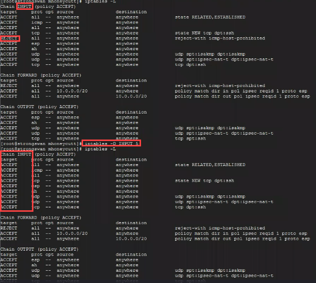
- Delete the two listed REJECT rules by running “iptables -D SECTION_NAME position#”. For example, in the screen shot below, the REJECT under INPUT is the 5^th^ rule down, so the command to delete it is “iptables -D INPUT 5”. Notice after running the command the REJECT rule under INPUT is no longer present.
-
To delete the REJECT under FORWARD, run “iptables -D FORWARD 1” as it is in position 1.
-
Run the command service iptables save
-
Run systemctl restart iptables
-
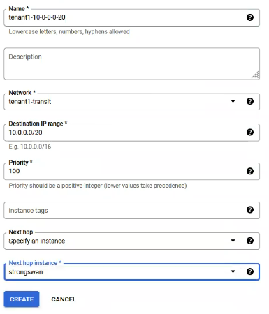
In the GCP console in the tenant project navigate to VPC Network -> Routes and click CREATE ROUTE.
-
Enter the following:
-
Name: tenantname-networkcidr
-
Network: tenantname-transit
-
Destination Range: IP CIDR range in the SDDC for the tenant
-
Priority: 100
-
Next Hop: Specify an instance
-
Next Hop Instance: The StrongSwan VM.
-
Click CREATE
-
Configure IPSec VPN in NSX and Configure Tenant Firewall Rules #
The following steps describes the steps required to create a CDs instance if one does not already exist that the SDDC should be associated to.
-
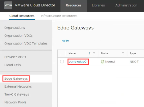
Log into Partner Navigator and navigate to Cloud Director Service and open the instance that is managing the GCVE SDDC.
-
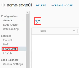
In the left pane click Edge Gateways and in the right pane click on the name of the tenant’s edge.
- Click on IPSec VPN and then click NEW.
-
Enter the following:
-
General Settings:
-
Name: Name the IPSec tunnel such as tenantname-gcve-ipsec
-
Click NEXT
-
-
Peer Authentication Mode:
-
Authentication Mode: Pre-Shared Key
-
Pre-Shared Key: Enter the PSK used for the tunnel
-
Click NEXT
-
-
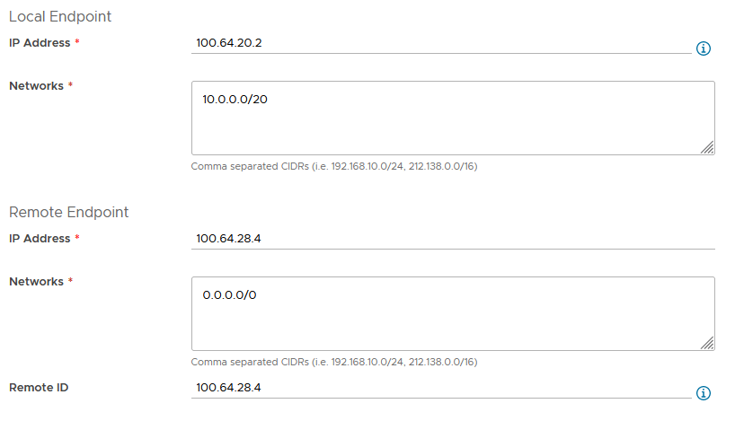
Endpoint Configuration:
-
Local Endpoint:
- IP Address: Local IP address of the tunnel (edge external network address) - Networks: Local network CIDR(s) for the tunnel -
Remote Endpoint:
- IP Address: Remote IP address of the VPN appliance - Networks: 0.0.0.0/0- Remote ID: Remote IP address of the VPN appliance
-
-
-
Click NEXT, then click FINISH to save the IPSec tunnel configuration.
-
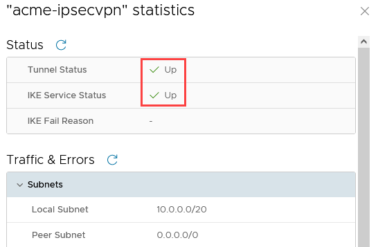
Click on VIEW STATISTICS.
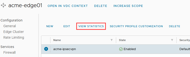
- After a few moments, the tunnel should show the Tunnel Status and IKE Service Status as Up.
-
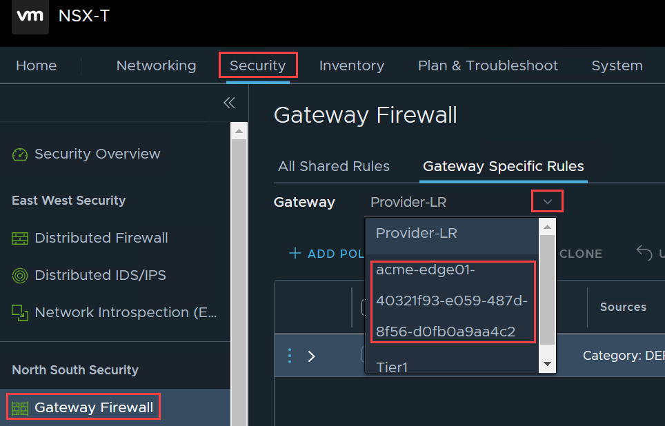
Log into the GCP provider jump host, navigate the NSX URL and log in as admin.
-
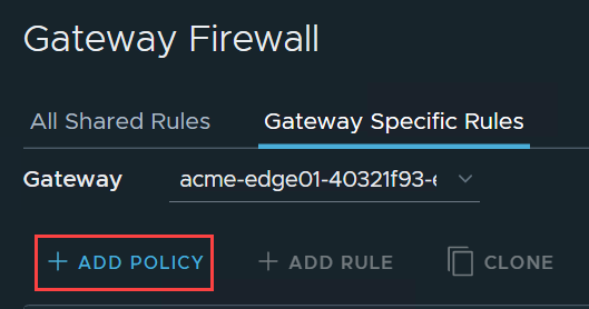
Click the Security tab, then in the left pane select Gateway Firewall, and in the right pane click the Gateway dropdown and select the tenant’s T1 to add the firewall rule to.
- Click ADD POLICY.
- Click in the Name box for the policy and provide a name such as “TenantName Tenant Rules”.
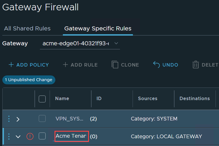
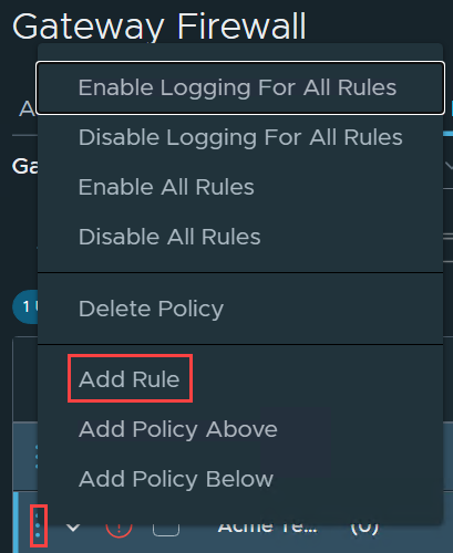
- Click the three horizontal dots to the left of the policy name and select Add Rule.
-
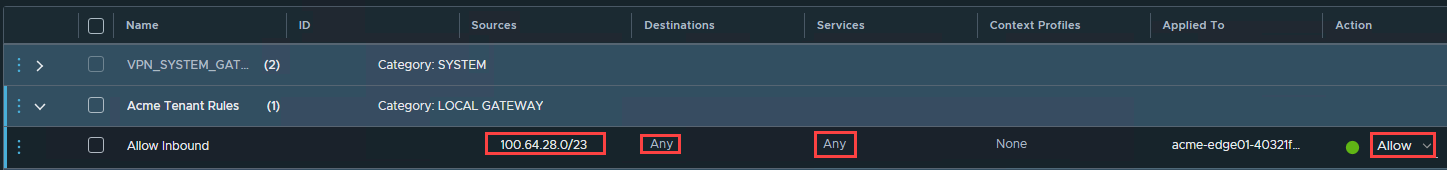
Enter the following:
-
Sources: Add the remote GCP tenant project’s CIDR block
-
Destination: Select Any for any local network or alternatively it can be locked down to a single CIDR
-
Services: Any (or filter to specifics if desired)
-
Action: Allow
-
-
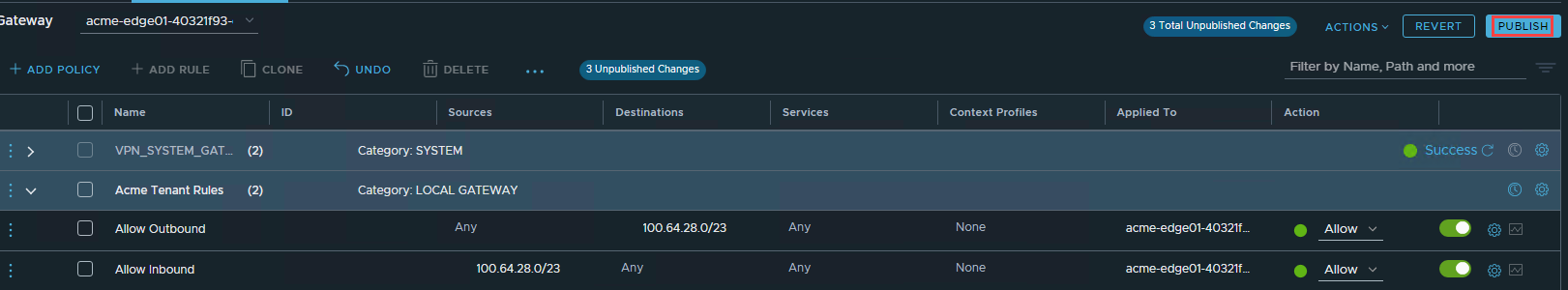
Add another rule called Allow Outbound and set the following:
-
Sources: Select Any for any local network or alternatively it can be locked down to a single CIDR
-
Destination: Add the remote GCP tenant project’s CIDR block
-
Action Allow
-
Once ready, click PUBLISH.
-
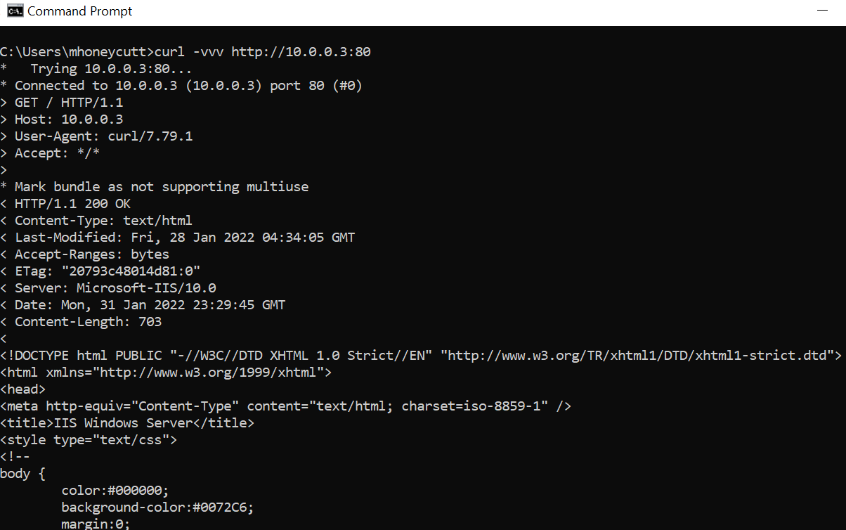
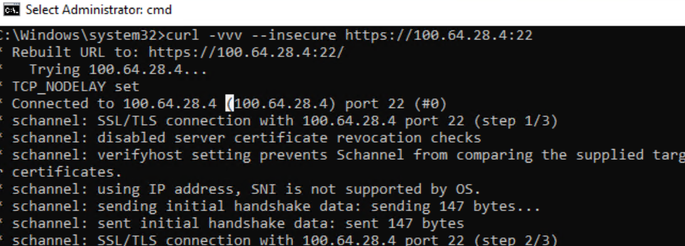
- Test the tunnel connectivity by deploying an instance in the GCP tenant project that was configured for the tunnel and the tenant in the SDDC to confirm it is functioning. Here we see that SSH/HTTP is connected between both tenant workloads.
Peer Existing Customer VPC #
The following section describes the steps required to pair a tenant owned customer VPC to an existing customer VPC. This step is optional as a customer may not have an existing GCP project.
The steps below will require information from the customer and given to the customer to complete the peering process.
Configure Provider Owned Customer VPC for Peering #
The following steps describes the steps required to peer the provider owned customer VPC to an existing customer owned VPC to enable connectivity between them.
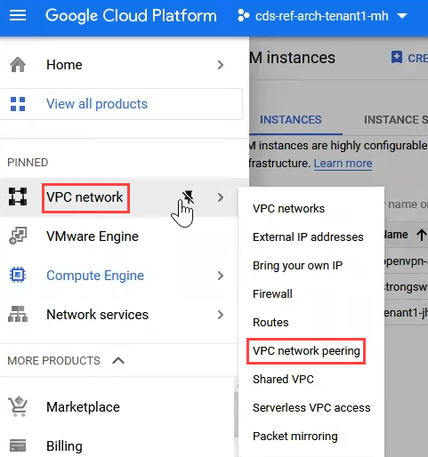
- In the GCP console, switch to the tenant to configure project and go to VPC Network -> VPC Network Peering.
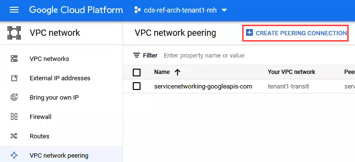
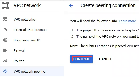
- Click CREATE PEERING CONNECTION.
- Click CONTINUE.
-
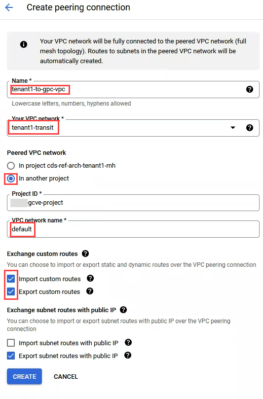
Enter the following:
-
Name: name the VPC connection something obvious such as “tenantname-to-gpc-vpc”
-
Your VPC Network: Select the tenant’s transit network
-
Peered VPC Network: In another project
-
Project ID: The name of the customer owned project
-
VPC Network Name: The default network name in the customer’s project
-
Exchange Custom Routes: Ensure both Import and Export custom routes are checked
-
Exchange Subnet Routes with Public IP: Select Export subnet routes with public IP
-
Click CREATE
-
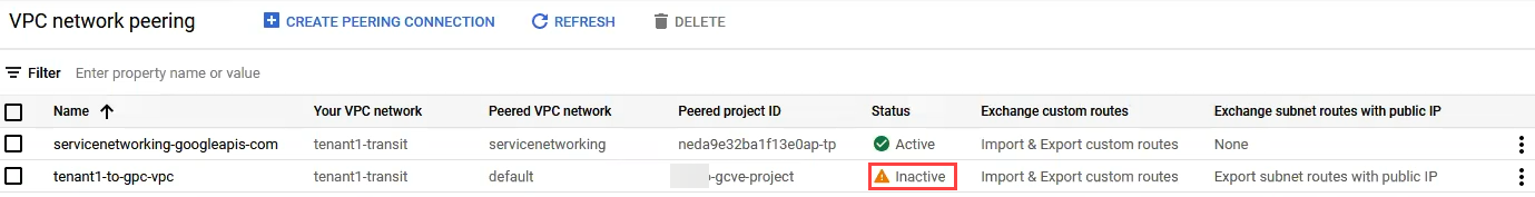
- The status of the peering will show with a Status of Inactive until the peering process is completed on the customer VPC side.
Customer to Configure the Customer Owned VPC for Peering #
The following steps describes the steps required to peer the customer owned VPC to the provider owned customer VPC to enable connectivity between them.
-
Complete the same process as shown in the previous step and provide the customer the following information to complete the peering:
-
Peered VPC Network: In another project
-
Project ID: The name of the provider owned customer project
-
VPC Network Name: The default network name in the tenant owned customer’s project “tenantname-transit”
-
Exchange Custom Routes: Ensure both Import and Export custom routes are checked
-
Exchange Subnet Routes with Public IP: Select Export subnet routes with public IP
-
Click CREATE
-
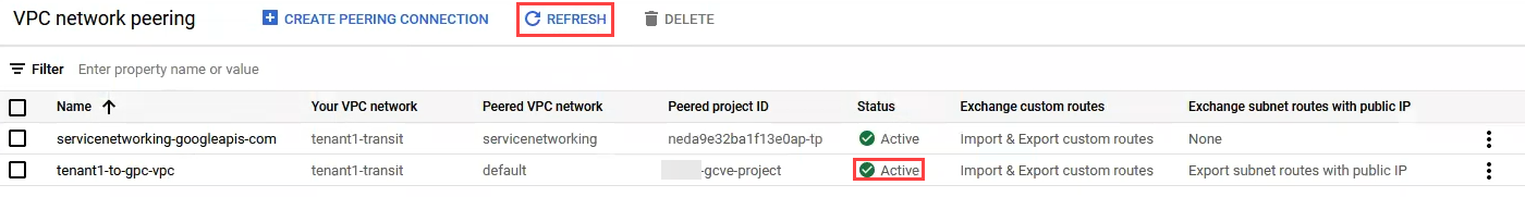
-
Once the customer has completed the peering process, click REFRESH on the VPC network peering page and the Status should change to Active.
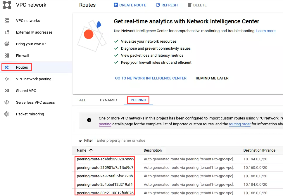
- Click on Routes on the VPC Network page, then click on the PEERING tab and it should display a list of peering routes discovered through the peering process.
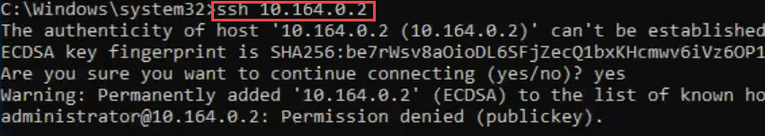
- To test the connectivity, try to SSH/ping from a workload on the customers GCVE environment into a workload in the GCP peering VPC. A firewall rule will need to be in place on the customer’s VPC side allowing the connectivity if it is not already present.
Setup NAT VMs for Internet Access (Optional) #
Note that this section is optional and only required if the customer will have Internet traffic egressing from the provider owned customer project.
The following section describes the steps required to setup a group of VMs for NAT for Internet access for workloads within GCVE.
These steps are required if the Internet access is egressing from the provider owned customer project or if a customer is routing all traffic to their peered project. The NAT VMs should be created and configured in the project that Internet access is egressing from.
Prepare and Deploy NAT VMs #
The following steps describes the steps required to prepare the environment to deploy the VMs used for NAT for Internet access and should be run from the project where the traffic will egress using NAT’s and ILB’s based on GCP compute instances.
Another third party solution can be used for this part which is encouraged for more flexible configuration and easier day two operations.
Two NAT VMs will be deployed, one in a different AZ in the region for redundancy in an active/passive configuration. The machine size for the NAT VMs below is small for testing purposes, these should be sized appropriately based on the expected throughput.
The shell commands are embedded in the attached text document here. 
- In the project where the Internet traffic will egress, in the top blue bar, click the Cloud Shell icon to launch the shell.

-
Prior to copying the shell commands, do a find and replace and replace the following entries. Note: Be careful not to insert any extra spaces or carriage returns to avoid syntax errors.
-
Find: gcve-team-project ; Replace with: tenant-project-name (ex: tenant1-project)
-
Find: --subnet=cds-tenant01-us-west2 ; Replace with: --subnet=tenant-transit-subnet (ex: asia-southeast1)
-
Find: cds-tenant01 ; Replace with: tenant-transit-network (ex: tenant1-transit)
-
Find: -region=us-west2 ; Replace with: -region=project-region-name (ex: asia-southeast1)
-
Find: --zone=us-west2-a ; Replace with: --zone=project-region-az-a (ex: asia-southeast1-a)
-
Find: --zone=us-west2-b ; Replace with: --zone=project-region-az-b (ex: asia-southeast1-b)
-
Find: cds-natgw-startupscripts/nat_gateway_startup.sh ; Replace with: tenant-bucket-name/name_of_startup_script.sh (ex: tenant1-storage/nat_gateway_startup.sh)
-
Find: us-west2 ; Replace with: project-region-name (ex: asia-southeast1)
-
Fine: n1-standard-2 ; Replace with: name of properly sized instance type requried
-
-
If there are known instances with private Ips that need public Internet routing, run the command below to allocate public IP(s) to add to the NAT startup script prior to uploading. This would need to be done for each instance that needs incoming Internet traffic.
-
gcloud compute addresses create natgw-asia-southeast1-forwarding-external-01 --region asia-southeast1
- Change the region to match where the project is located
-
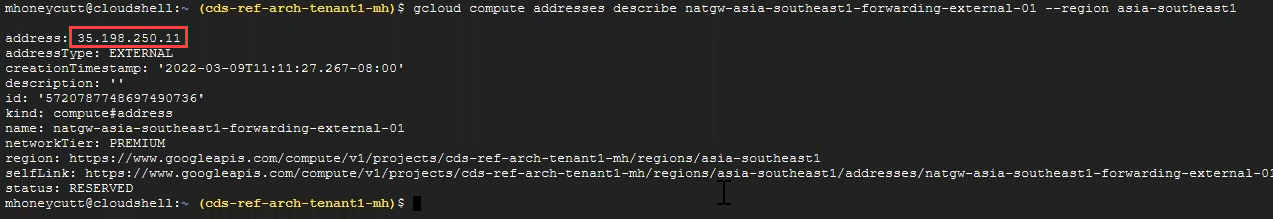
Run the following command to display the IP that was allocated:
- gcloud compute addresses describe natgw-asia-southeast1-forwarding-external-01 --region asia-southeast1
-
-
Note this IP address to use in the startup script section below.
-
Create a storage bucket and save the startup script:
-
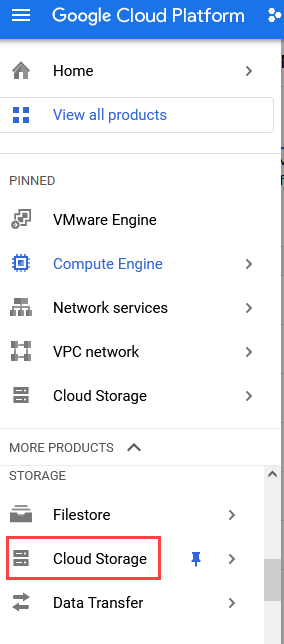
Under the Google Cloud Platform menu, click Cloud Storage.
-
Click CREATE BUCKET.
-
Enter a name for the bucket such as “tenantname-storage” and click CREATE.
-
Open the below attached text file.Replace the text line “iptables -t nat -A PREROUTING -d $nlb_vip -i ens4 -j DNAT --to $test_endpoint_ip " for $nbl_vip with the public IP allocated for the workload requiring incoming Internet connections and $test_endpoint_ip with the private IP of the workload servicing the traffic (web server, etc).
-
If there as a public IP address allocated for a device that needs incoming Internet traffic, replace the line below with the public IP that was allocated and the correct private IP. Also delete the other line if it is not required; this iptables command would be a line for each public IP that will be forwarded. Change the public IP after -d to what was previously allocated and the IP after DNAT to the private IP of the host (not the T1 gateway, the private IP of the device, such as the Windows server)
- iptables -t nat -A PREROUTING -d 35.236.94.128 -i ens4 -j DNAT --to 10.0.0.3
-
Save the file locally as “nat_gateway_startup.sh” or something similar and close it.
-
Back in the storage bucket that was created, click into the bucket name, and then click UPLOAD FILES.
-
Upload the nat_gateway_startup.sh file that was saved locally.
-
-
From the text file with the shell commands, copy and paste the contents to create and configure the NAT and ILB:
-
Open the GCP cloud shell
-
Copy and paste first line into Google cloud shell to create the SSH firewall rule.
-
Skip the two lines that being with “glcoud compute networks” as they should already be created.
-
Copy the two lines with “gcloud compute addresses create” and paste those into the shell and hit enter to create the addresses.
-
Copy the next two lines with “nat_#_ip=$” and paste those into the shell and hit enter to set the NAT IP variables.
-
Copy the block commands with “gcloud compute instance-templates” and paste those into the shell and hit enter the create the templates.
-
Copy the lines “gcloud compute health-checks create” down through the three lines with “glcoud compute firewall-rules create” and paste them into the shell and hit enter to create the health check and firewall rules.
-
Copy the lines “gcloud compute instance-groups managed create” and paste them into the shell and hit enter to create the instances.
-
Copy the line “gcloud compute health-checks create” and paste it into the shell and hit enter to create the next health check.
-
Copy the line “gcloud compute backend-services create” and paste it into the shell and hit enter to create the natgw backend.
-
Copy the two lines “gcloud compute backend-services add-backend” and paste them into the shell and hit enter to add the two nats to the backend that was just created.\
-
The lines under Just Outbound NAT can be skipped if the customer has both incoming and outgoing traffic.
-
Copy the line “gcloud compute forwarding-rules create” and paste it into the shell and hit enter to create the forwarding rule.
-
Copy the lines for “gcloud compute routes create” and paste them into the shell and hit enter to create the two routes.
-
Under Public IP Exposure settings, copy the line “gcloud compute backend-services create” and paste it into the shell and hit enter to create the backend service for the ILB.
-
Copy the two lines with “gcloud compute backend-services add-backend” and paste them into the shell and hit enter to add the hosts to the backend.
-
If a public IP was allocated previously for an existing workload, copy the last line with “gcloud beta compute forwarding-rules” and paste it into the shell and hit enter to add the forwarding rule.
-
Note: When adding a new public IP for a workload, the last two lines in this file would need to be reran to allocate the public IP, then create a forwarding rule for it.
-

Configure Firewall and Routes #
The following steps describes the steps required create the firewall rule and routes required to load balancer Internet traffic across the 3 NAT internet gateways that were previously deployed.
The default routes for the NAT will use instance tags to keep from the routes leaking back into the GCVE environment. This tag can be whatever the provider desires, but it must be uniform across all 3 routes that will direct traffic to the Internet via the NAT gateways. This applies to the routes created below for nat1, nat2, and nat3. This tag must match the one used on the instances created previously (VPN host).
-
In the provider owned customer tenant, navigate to Cloud shell and enter the following command to allow intervpc communication, changing the “—network=tenant1-transit” to the customer’s transit network.
- gcloud compute firewall-rules create intervpc-communication1 --direction=INGRESS --priority=100 --network=tenant1-transit --action=ALLOW --rules=all --source-ranges=10.0.0.0/8,172.16.0.0/12,192.168.0.0/16,100.64.0.0/16 --target-tags=natgw
-
Create a firewall rule for the NAT health check by running the following command, changing the “—network-tenant1-transit” to the name of the customer’s transit network.
- gcloud compute firewall-rules create "natfirewall" --allow tcp:80 --target-tags natgw --source-ranges "209.85.152.0/22","209.85.204.0/22","35.191.0.0/16" --network=tenant1-transit
-
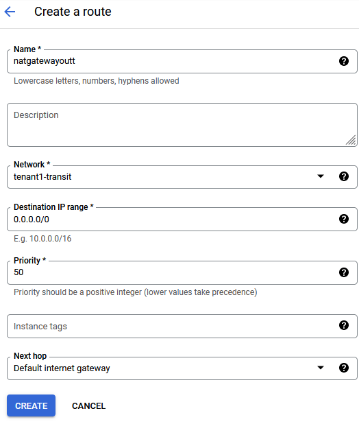
Click on Routes in the left pane and click CREATE ROUTE and enter the following:
-
Name: natgatewayout
-
Network: tenantname-transit
-
Destination IP range: 0.0.0.0/0
-
Priority: 50
-
Next Hope: Default internet gateway
-
Click CREATE
-
-
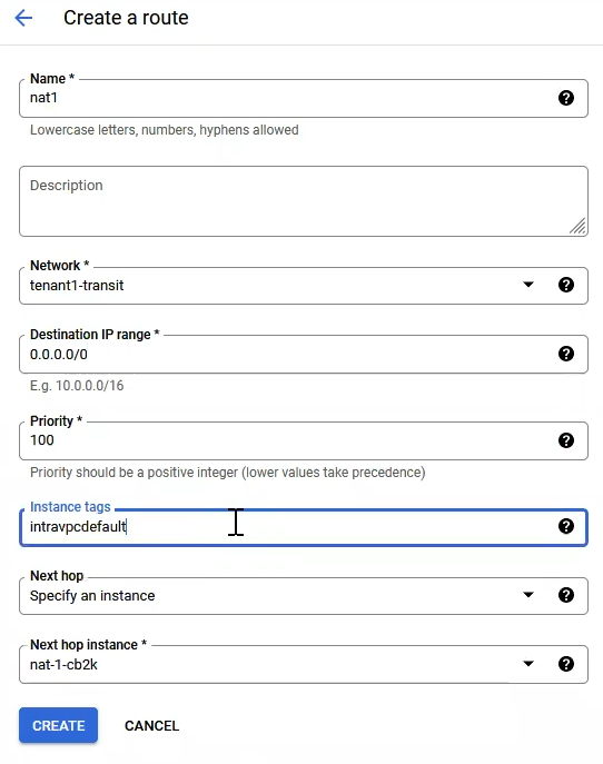
Click CREATE ROUTE and enter the following:
-
Name: nat1
-
Network: tenantname-transit
-
Destination IP range: 0.0.0.0/0
-
Priority: 100
-
Instance tags: intravpcdefault
-
Next Hop: Specify an instance
-
Next Hop Instance: nat-1
-
Click CREATE
-
-
Create two more routes, one named nat2 and one nat3 with the same priority of 100 and specify the next instance as nat-2 and nat-3 respectively for their routes as well as the same instance tag.
-
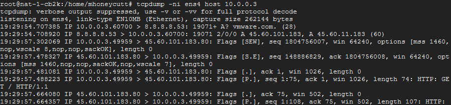
To test the functionality of the NAT VMs:
-
Open an SSH session to each NAT VM and installing tcpdump with “sudo apt install tcpdump -y”
-
On each host, run tcpdump with a filter set to the IP of a test workload in GCVE with “tcpdump -ni ens4 host ip_of_workload”
-
On the GCVE workload, repeatedly curl a public URL such as vmware.com and the traffic hits should spread across the three NAT VMs.
-
Conclusion #
At this point, the VMware Cloud Director service Instance is ready to deploy tenant VMs. For more information see the documentation for VMware Cloud Director service and VMware Cloud Director.